Hub-and-Spoke Architecture with Zero Trust Networking
Simplifying Networking, Security, and Cost at Scale.
Introduction#
Most teams start with per-environment networks; Dev, QA, and Prod each with their own NAT, firewall, DNS, and load balancers. This approach is simple at first but quickly becomes costly, inconsistent, and difficult to secure.
In this post, I’ll walk through how we have adopted a hub-and-spoke network architecture secured with Cloudflare Zero Trust (ZTN) for a enterprise project at Surge Global. I’ll cover why we chose this model, how traffic flows, the security benefits, and real-world deployments, including industry practices from Google Cloud and Surge Global.
The Problem: Per-Environment Networking#
Each environment duplicating infrastructure looks like this:
- NAT, firewall, load balancer, DNS repeated in every environment
- Multiple ingress/egress points to manage
- Firewall policies scattered and inconsistent
- Logs and monitoring fragmented
- Higher costs and configuration drift risks
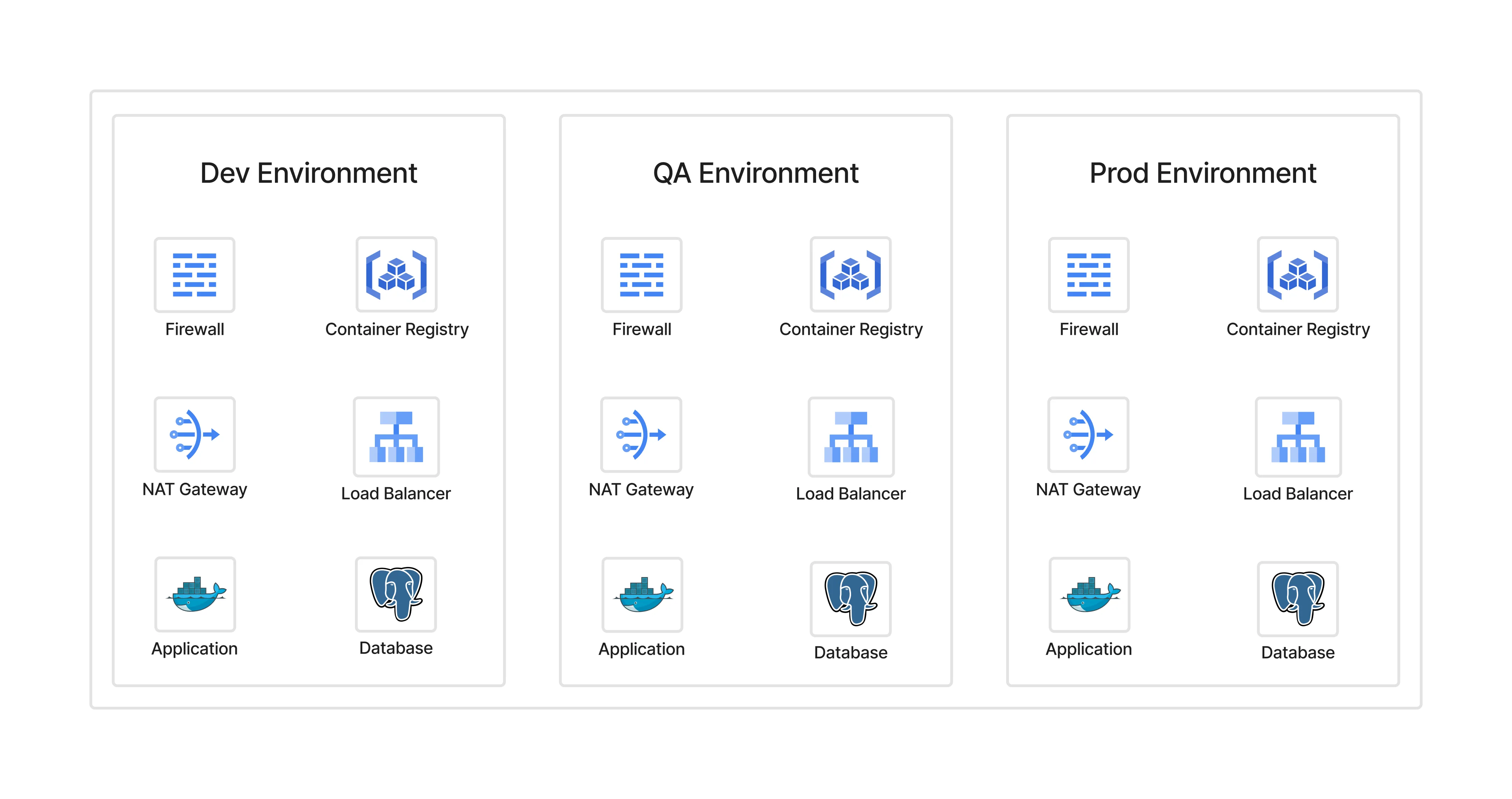
What seems easy for a small setup becomes a bottleneck at scale.
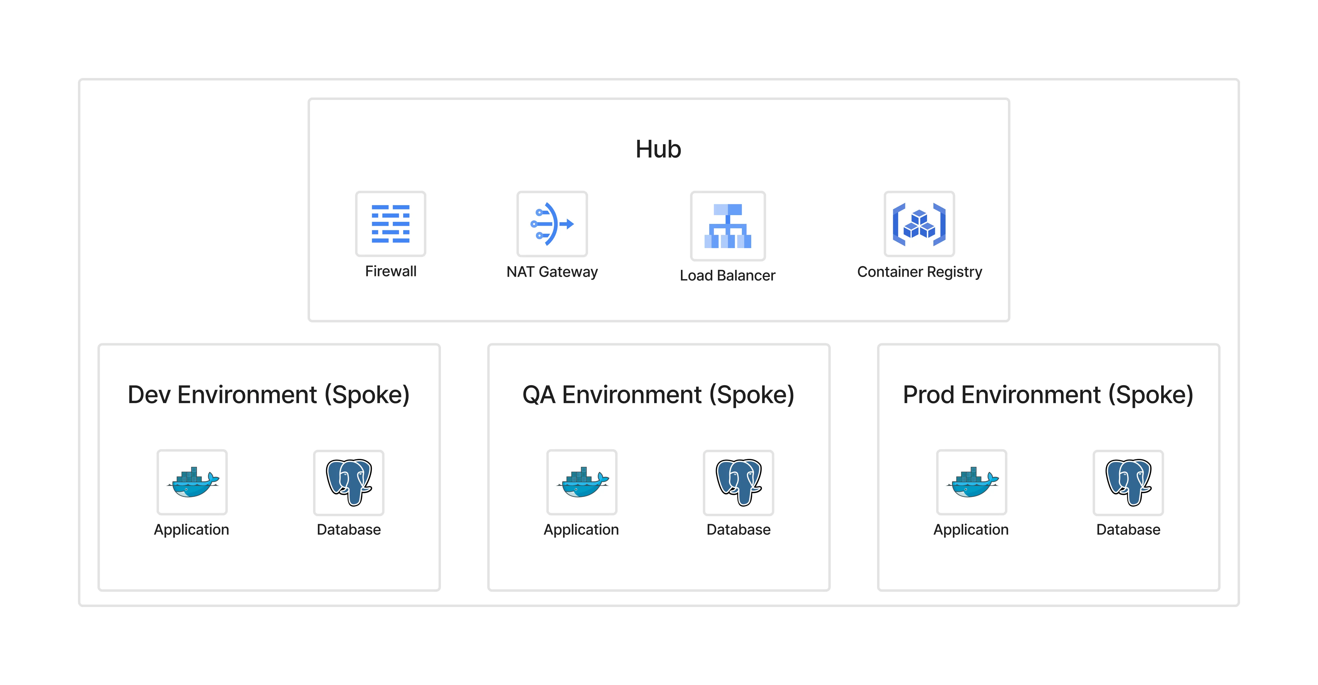
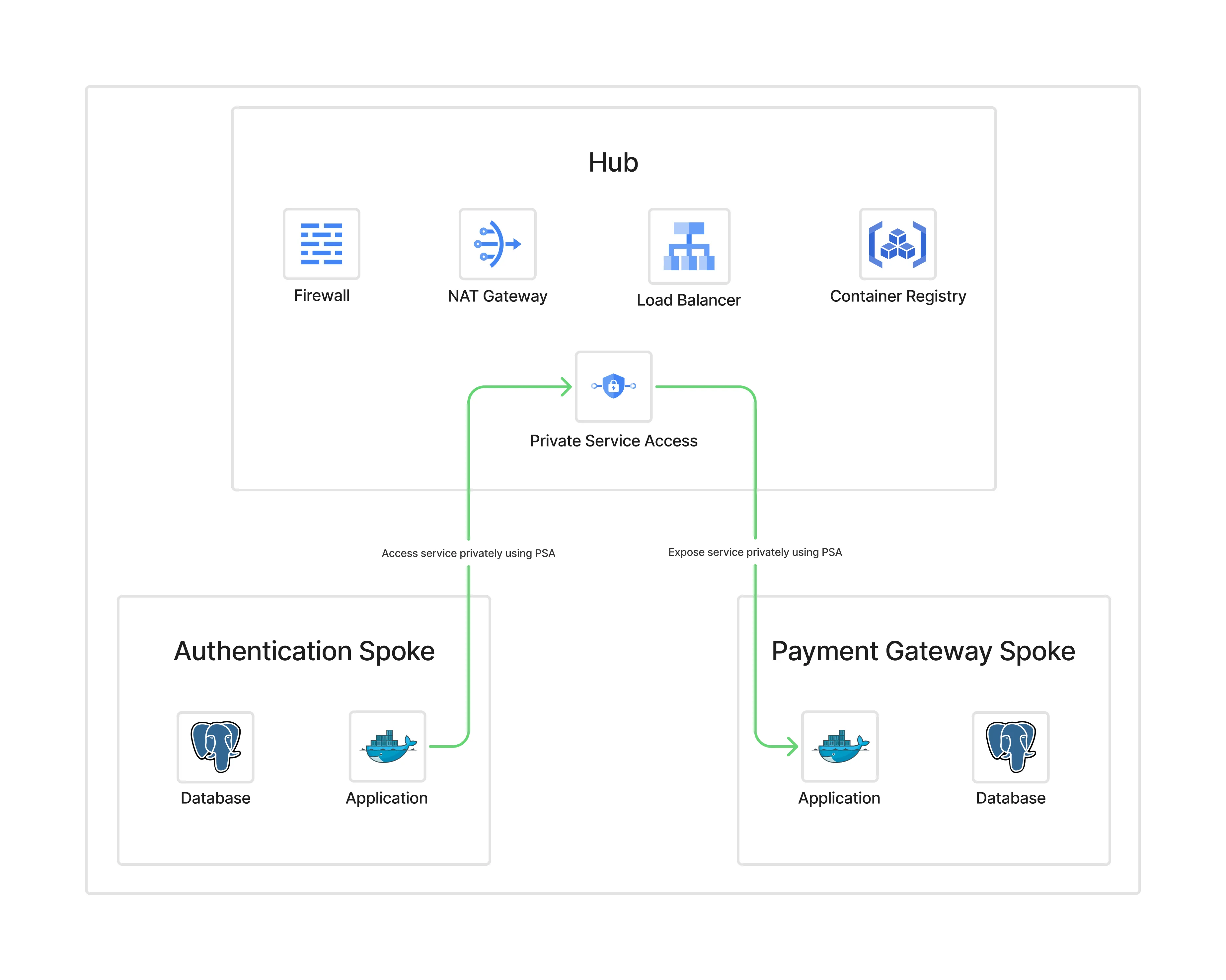
The Solution: Hub-and-Spoke Architecture#
In a hub-and-spoke model:
- Hub contains shared services (NAT, firewall, DNS, load balancer).
- Spokes are isolated environments (Dev, QA, Prod) that remain private.
- All ingress and egress flows through the hub.
Benefits:
- Centralised firewall and NAT management
- Uniform policies
- Reduced cost (one NAT, one firewall instead of many)
- Easier audits and observability
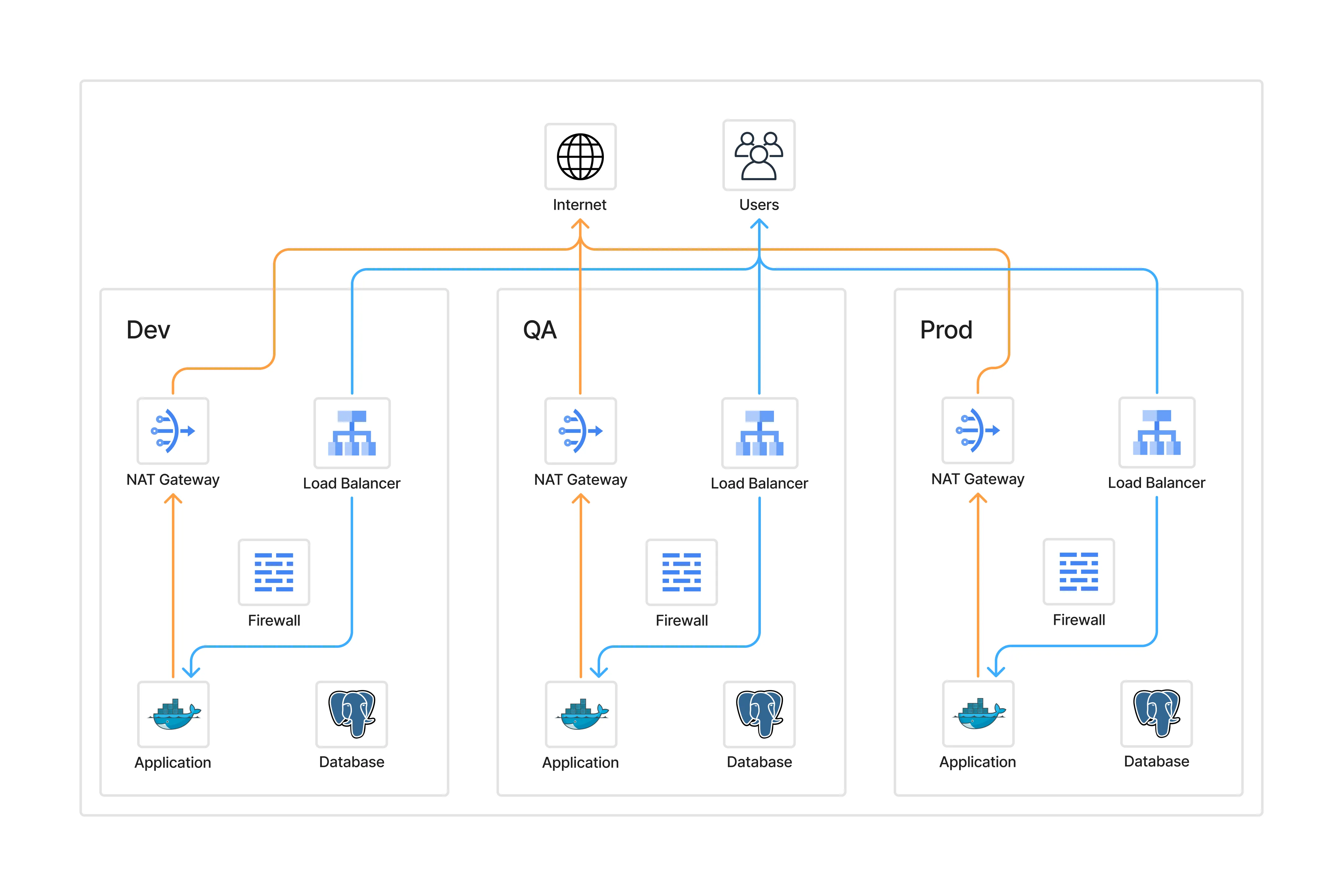
Traffic Flows#
Per-Environment (Monolithic) Model
- Public traffic hits environment-specific load balancers.
- Applications egress through separate NATs.
- Each environment manages its own firewall rules.
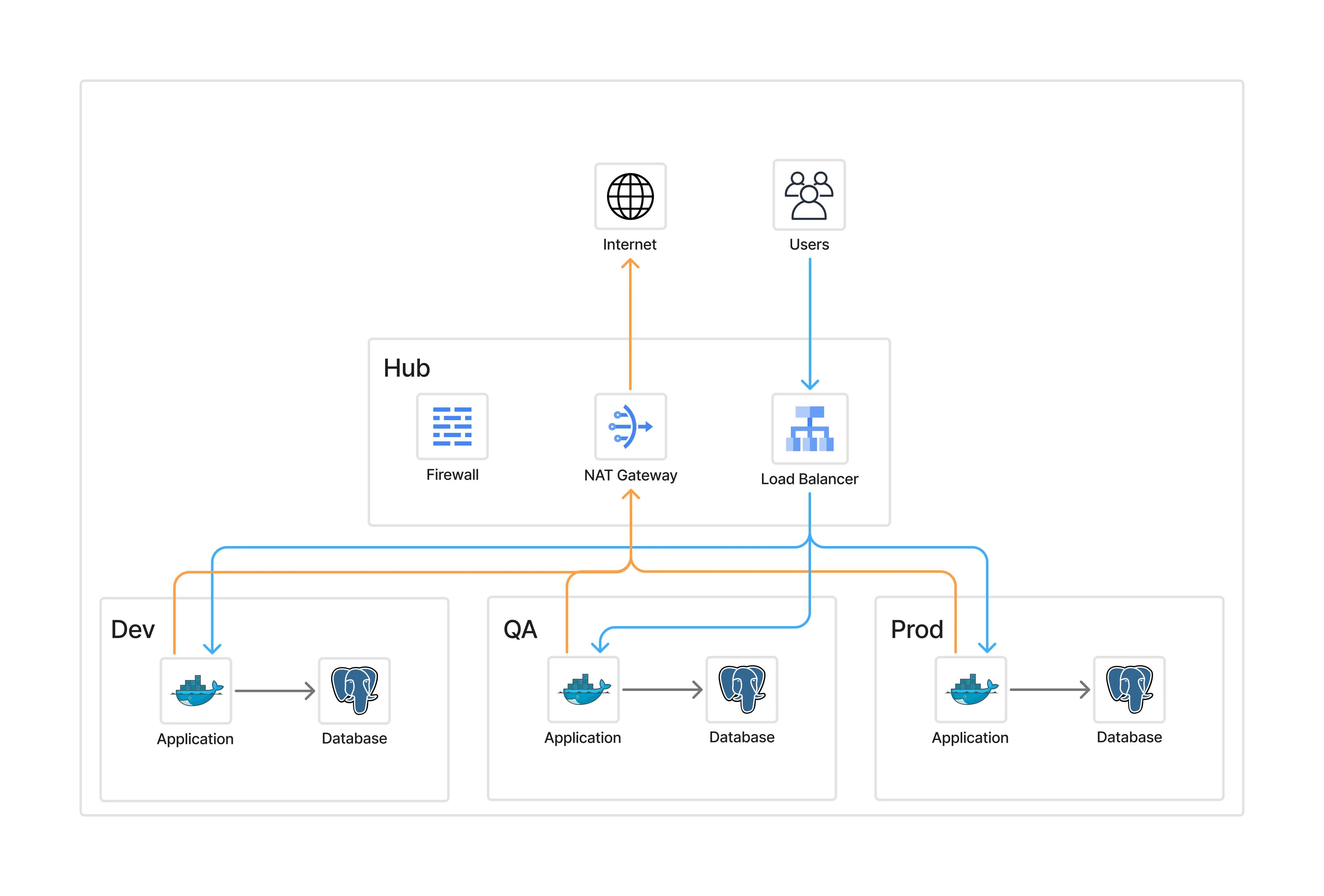
Hub-and-Spoke Model
- Public traffic flows → hub load balancer → spokes.
- Outbound traffic flows → spokes → hub NAT → internet.
- Developers and admins authenticate via Zero Trust before reaching any spoke.
Introducing Cloudflare Zero Trust#
Zero Trust changes the game:
- Removes the need for public IPs
- Provides identity- and context-aware access
- Replaces VPNs with granular, policy-driven access
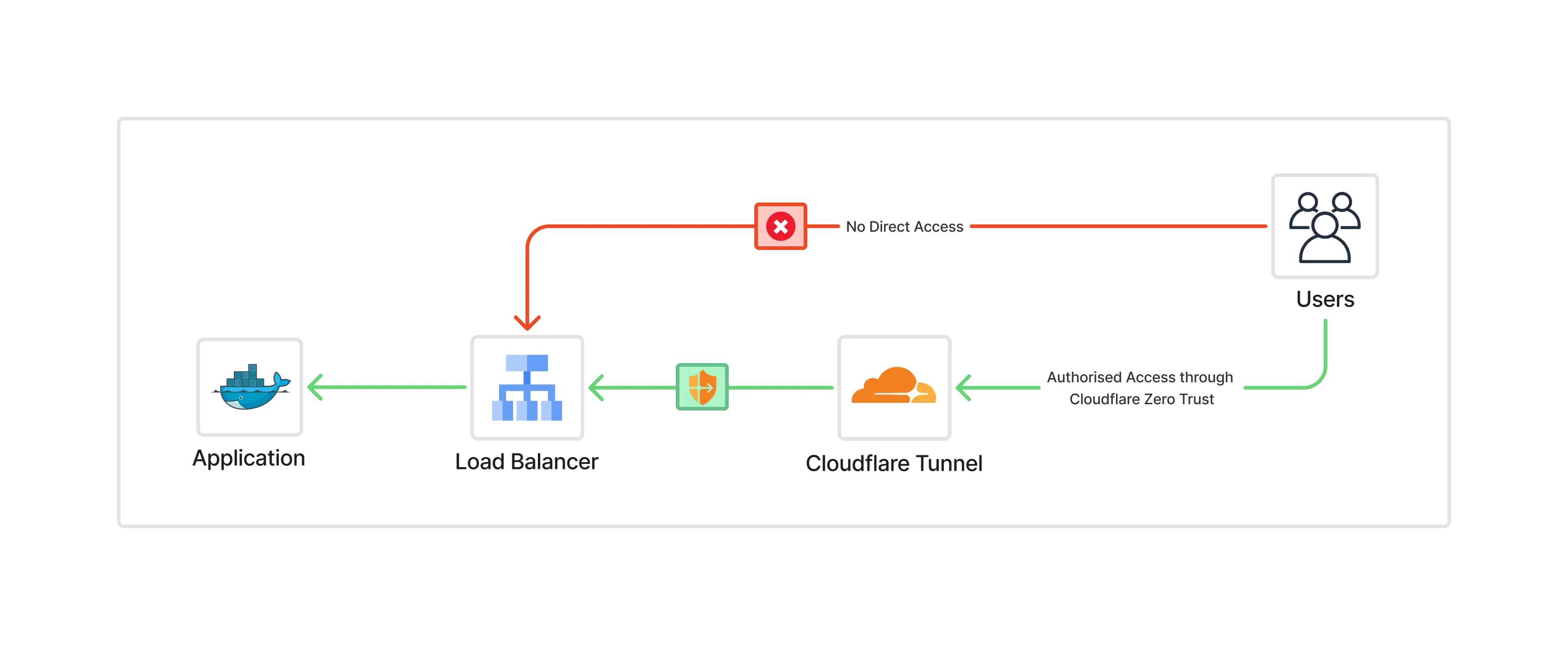
With Cloudflare ZTN, neither the hub nor the spokes need public exposure. Access flows through Cloudflare’s global edge, authenticated per user/device/policy.
Deploying the Cloudflare Connector#
Getting started is simple. Run the cloudflared daemon on a hub VM:
sudo cloudflared service install <token>Then apply a tight firewall rule to allow cloudflared to connect only to Cloudflare endpoints (TCP/UDP 7844).
From there, internal spokes no longer need public IPs; developer and admin access goes through Cloudflare, while production traffic can keep using the external load balancer.
{
  name        = "allow-cloudflared-to-endpoints"
  description = "Allow cloudflared egress to the cloudflare endpoints"
  action      = "allow"
  direction   = "EGRESS"
  priority    = 501
  dest_fqdns = [
    "region1.v2.argotunnel.com",
    "region2.v2.argotunnel.com",
    "cftunnel.com",
    "h2.cftunnel.com",
    "quic.cftunnel.com"
  ]
  layer4_configs = [
    {
      ip_protocol = "tcp"
      ports       = ["7844"]
    },
    {
      ip_protocol = "udp"
      ports       = ["7844"]
    }
  ]
}
See the Cloudflare Docs – Tunnel with Firewall.
Final Architecture#
The final state looks like this:
- Hub centralises NAT, firewall, and load balancers
- Spokes are fully private
- Cloudflare Tunnel provides secure developer/admin access
- End users reach production apps only via the external load balancer
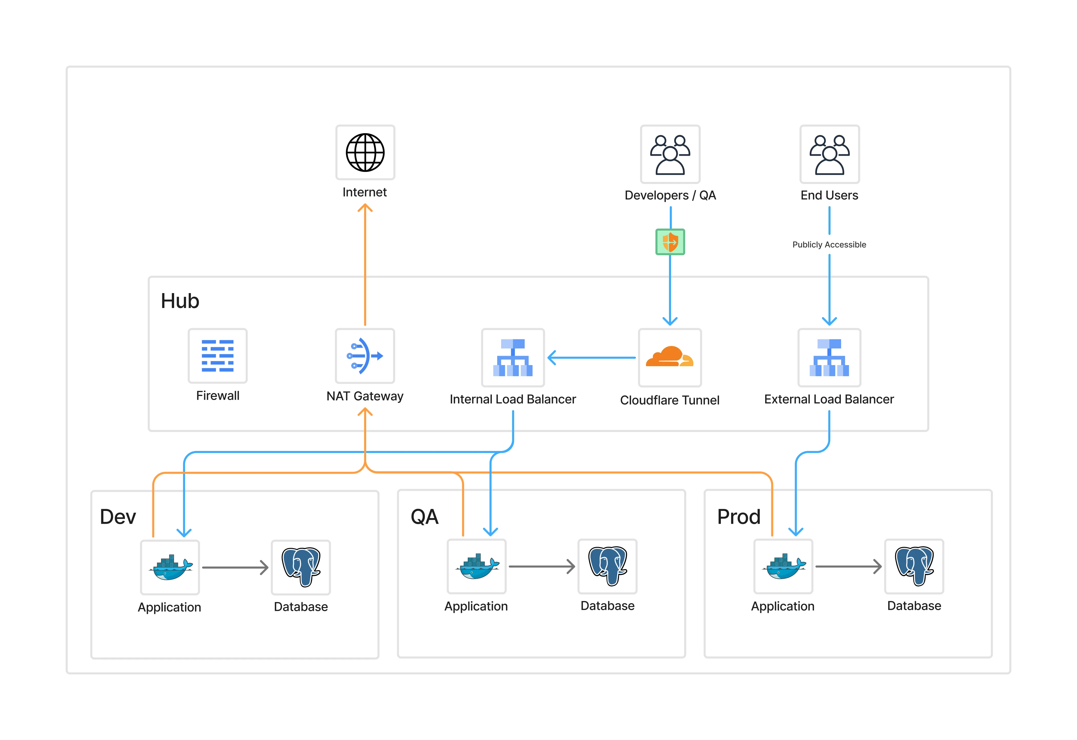
This pattern isolates environments, simplifies operations, and eliminates public exposure.
Real-World Examples#
Surge Global#

We deployed this model at an Enterprise project at Surge Global, our first company project to use hub-and-spoke. It centralised firewall/NAT/DNS, used Cloudflare ZTN for non-prod environments, and reduced both cost and operational overhead.
Industry Reference#
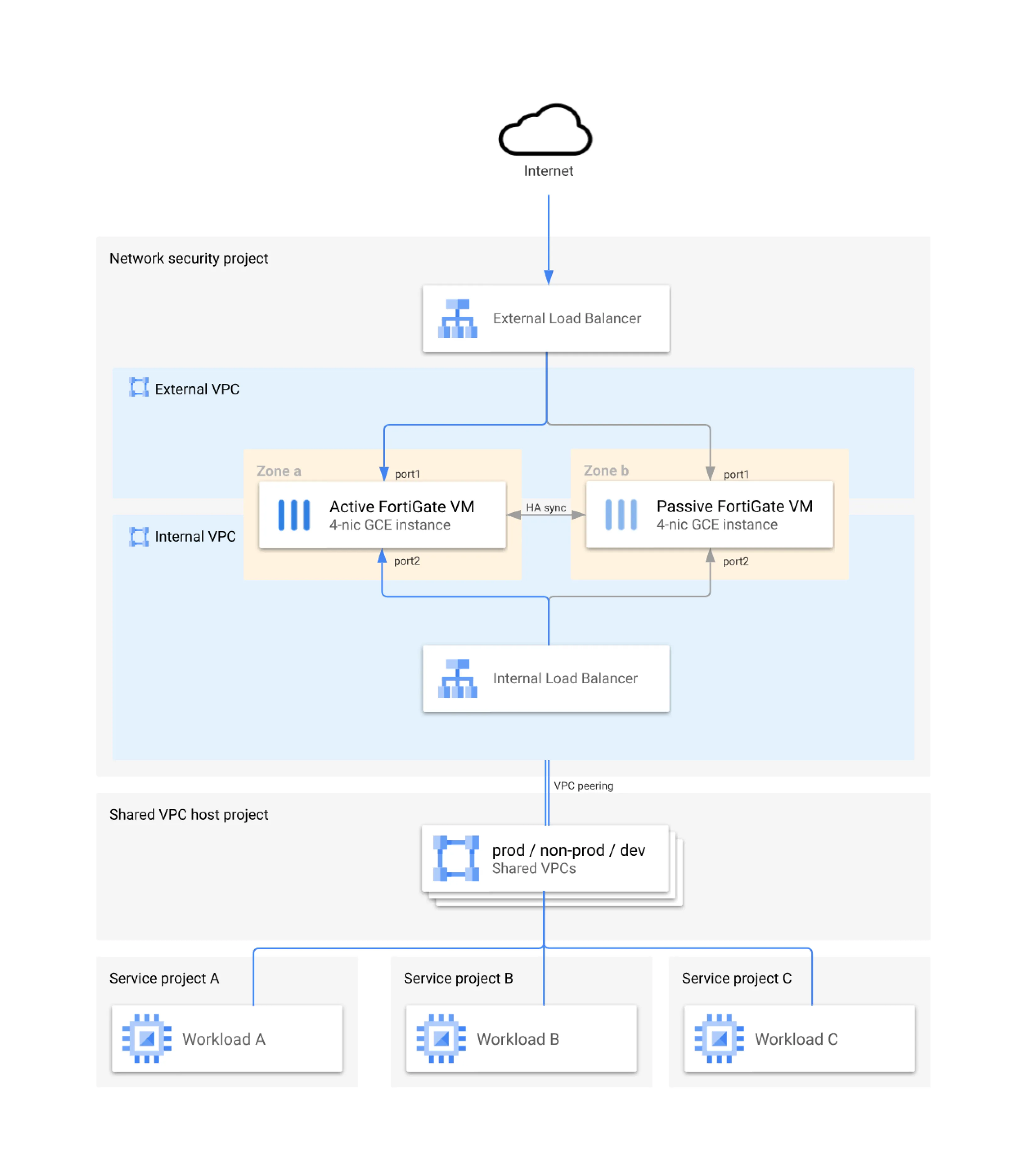
Google Cloud publishes a reference hub-and-spoke model with Fortinet appliances protecting the hub. This design mirrors what the Surge Global Project runs today, showing that hub-and-spoke + Zero Trust is now an industry standard for secure, large-scale environments.
See the Google Cloud – Fortinet Reference Architecture.
Tradeoffs#
No design is free:
- Routing is more complex than per-environment
- Hub is a critical dependency → must be highly available
- Steeper learning curve for teams
- Centralisation means changes affect all environments
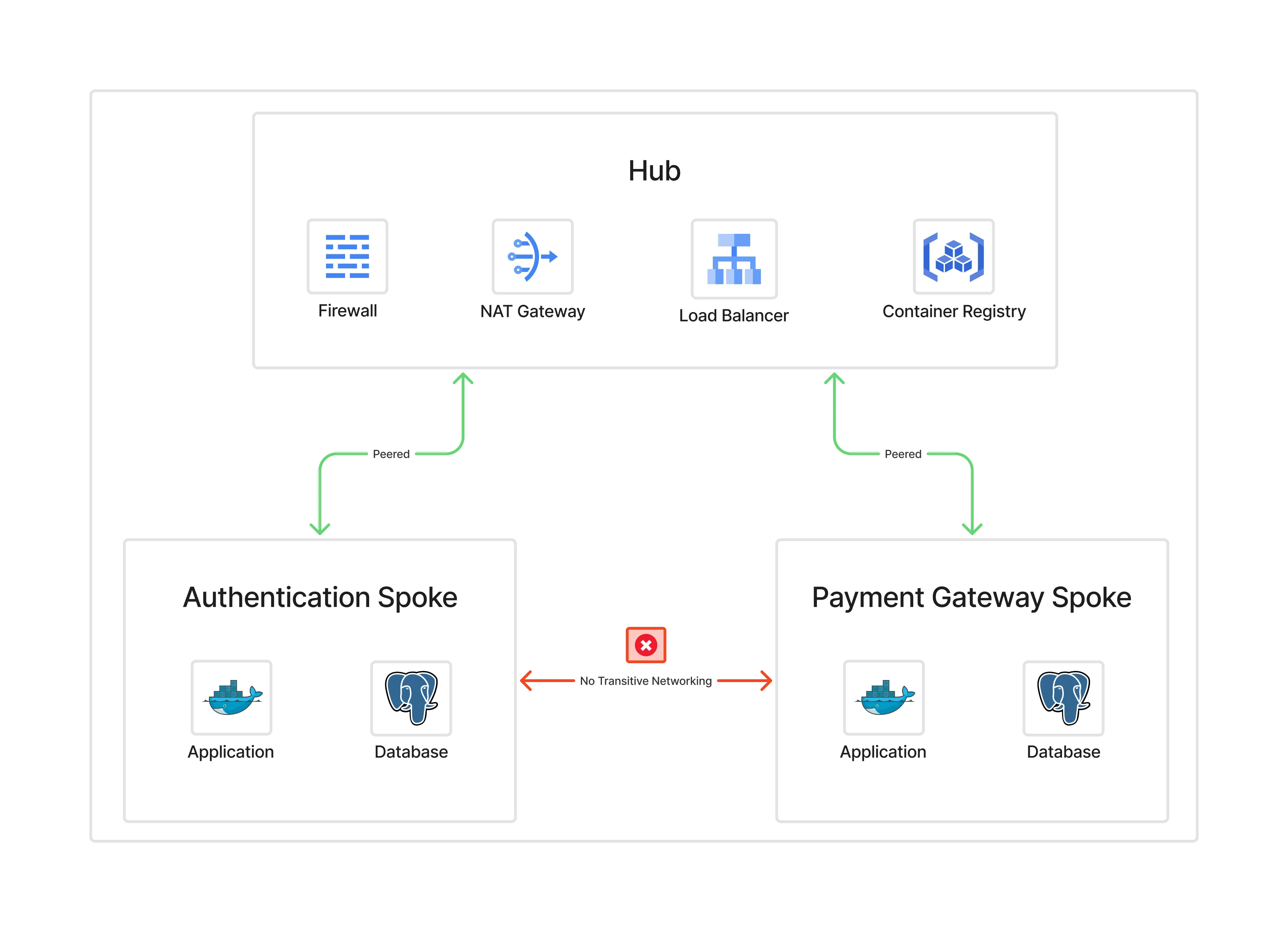
Key Considerations#
When deploying hub-and-spoke, plan for:
- IP address space (avoid overlaps)
- Non-transitive peering (spoke-to-spoke must go via hub, or use Shared VPC / PSC / NCC)
- Scaling limits (peering, firewall throughput,
cloudflaredsizing) - High availability (multi-zone, multi-region hub design)
Hands-On Resources#
To make this concrete, I’ve published Terraform examples that show three ways to deploy Cloudflare Tunnels in hub-and-spoke:
- Full IaC with Kubernetes (complete automation)
- Manual + Kubernetes (use existing tunnel, deploy cloudflared only)
- Manual VM on GCP (run cloudflared on Compute Engine)
Cloudflare Zero Trust Terraform templates (GitHub)